The reasons that closed transition units are preferable.
By Robert J. Wooddall
Some wye-delta starters for large motors can cause peak currents in the power system to exceed the normal trip settings of branch circuit breakers. It is the so-called "open transition" wye-delta starter that's the culprit. "Closed transition" starters do not permit this peak to occur. Both types are diagrammed in accompanying illustrations.
Wye-Delta starting requires, as the name implies, a switching of the motor windings from one connection (wye) to another (delta). Switching the motor from wye to delta by the open transition method allows it to be completely disconnected from the power source for a brief time period before being reconnected delta. Closed transition switching maintains connection of the motor to its source during the reconnection cycle.
High peak currents in the power system feeding an induction motor that is switched off and then suddenly switched on can cause unexpected disturbances in the form of circuit breaker tripping and fuse blowing. These high currents are of relatively short duration. One or two cycles is usually the time required for them to recede to a value below a level of disturbance. However, circuit breaker trips can operate in 1/4 to 1/2 cycle. The transient is therefore a problem involving protective devices and not especially one of system voltage drop.
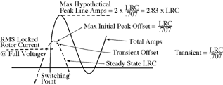
The peak value of current occurs when a contactor closes upon a critical point on the applied voltage wave.
Figure 1 shows a rough idea of how the maximum peak current magnitude may add up. It must be understood that this is "worst case" approximation and does not take into account factors which always exist to reduce these values. Theoretically, it is possible under worst conditions to have a peak current approximately equal to 2.83 times the motor locked rotor current when full voltage is applied with no existing flux. Now shown on Figure 1 is the effect of transient slope in reducing the current in the first 1/2 cycle.

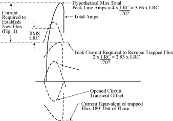
Figure 2 shows a rough idea of how it may be imagined that peak currents occur when there is flux in the motor equal to full voltage locked rotor flux but displaced 180 degrees. One may imagine that it is hypothetically possible to have a peak current of 5.66 times rated locked rotor current.

In the case of wye-delta starting, the existing flux, which has been generated by the wye connection, would be only the square root of 3 times that of the delta connection. (Flux being proportional to voltage.) The peak line current required to reverse this flux would then be the current equivalent of the existing flux, which would be
          (2 x 1/3 LRC)
              .707
or .944 X LRC. Adding this to the peak current to produce new flux would give a maximum peak 3.77 times LRC if we imaging the transitioning being accomplished so rapidly as to allow no loss of flux. Actually, transitioning cannot occur this fast and in the interim a further decay of flux occurs.
Motor time constants for ratings between 500 HP and 1000 HP range from 0.5 to 1.0 seconds, depending upon speed and voltage. To allow for a major decrease in flux would require time delay between opening and closing of contactors approximately 1/2 seconds of the 0.5 te motor. This should bring the flux down from the 1/3 condition to about .20. Maximum peak would then be about 3.39 times LRC. Of course, allowing one full second between contactors would bring the flux down further.
Fortunately, some practical work has been done in this field to give a perspective on the actual values of peak current that can be expected. Maginniss and Schultz of General Electric Company conducted differential analyser studies in 1944, documented in AIEE paper 44-175, which demonstrated that maximum peak current at stall is about 2.28 times RMS LRC, and maximum peak current with full trapped flux is about 4.4 times RMS LRC. This substantiates the theory that maximum trapped flux requires approximately twice current to reverse it. It also demonstrates that actually the peak hypothetical values are not to be expected in practice. Using the test values and evaluating them against the hypothetical values provides a basis for deciding what might be a "worst condition" for a particular application. A judgment can be made as to settings of circuit breaker trips and fuse ratings.
Comparing the theoretical values of peak currents with actual test values provides some useful factors. The actual peak is (2.28/2.83) X theoretical peak, or .79 X theoretical peak. For the trapped flux condition:
          Total peak = (2.83) (.79) x LRC +
          .79 (2 X peak amps equivalent of trapped flux).
For wye-delta starting peak amps equivalent of trapped flux =
          1/3 LRC = .472 LRC.
           .707
Therefore, actual total peak amps
          = 2.24 X LRC + .746 LRC
          = 2.986 X LRC.
Other values can be calculated for various conditions of trapped flux based on time delay.
Using locked rotor current as the basic parameter in place of full load current is necessary to prevent introducing too many unknowns. Motor locked rotor current is a readily available measure of motor performance under the conditions we are concerned with. The characteristics of mutual inductance, self inductance, flux linkage, and winding resistance are all summed up in the value of locked rotor current. The relationship between locked rotor current and full load current will vary between motors of different designs: speed, cage configuration, insulation spacing, air gap, etc. We can, therefore, predict peak currents in terms of LRC, but not in terms of full load current.
The benefit of closed transition wye-delta starting is two-fold. One, it maintains the motor connection to the power system to prevent a 180 degree displacement of flux. Two, it introduces series resistance which dampens the transient offset current during the step voltage increase. The 30 degree shift in flux, wye-to-delta, could cause an added value of current, but it is safe to say that this is canceled by the dampening effect of the eternal series resistor. The net effect is that peak current for closed transition will be no greater than that at stall, full voltage.
www.mastercontrols.com